A go-kart, from tube to telemetry
Two summers of fabrication in a workshop in İstanbul. It has a frame, a drivetrain and a working instrument cluster. It does not, at the moment, drive.
The problem
I wanted to build a vehicle from scratch, one where the frame geometry, the drivetrain choice and the instrumentation were all mine to get right or wrong. A kit or a restoration wouldn’t have given me that.
Design
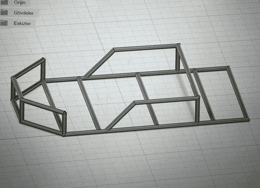
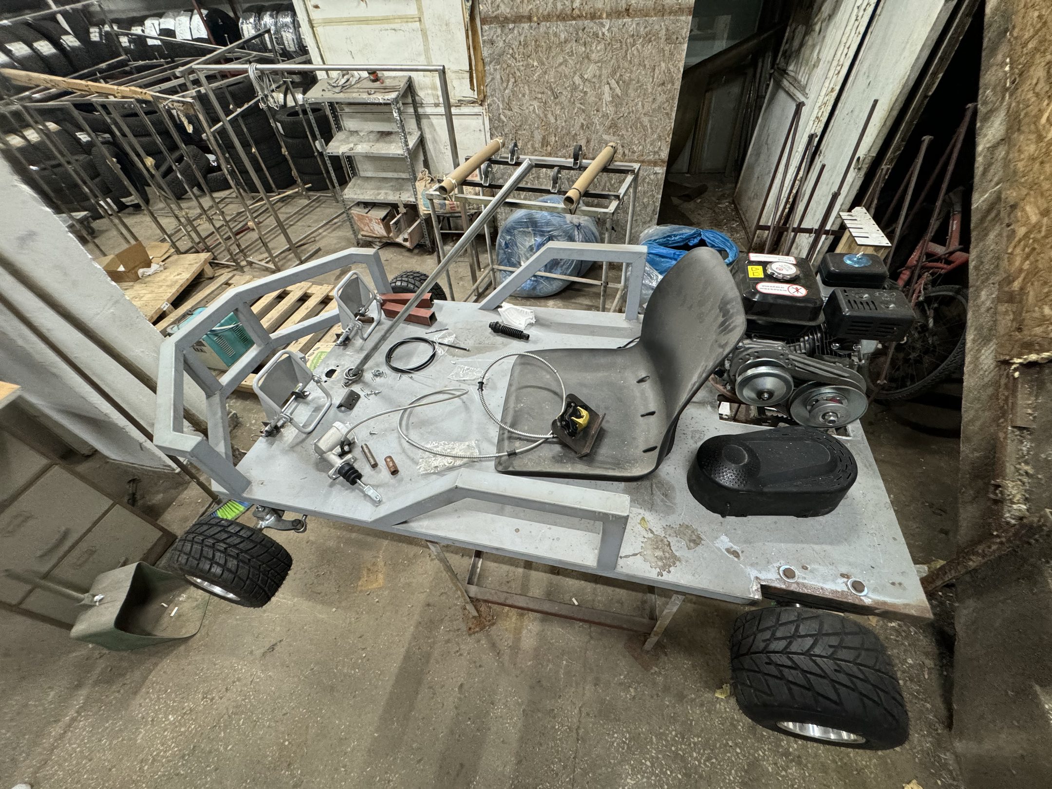
The frame was modelled in Fusion 360 first: a tube structure sized around a seat position, a rear axle line and an engine bay, with the floor pan as a stressed member rather than a cover.
Fabrication
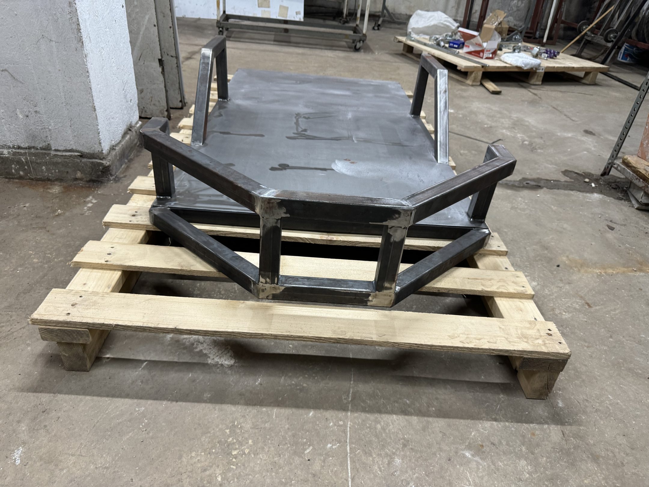
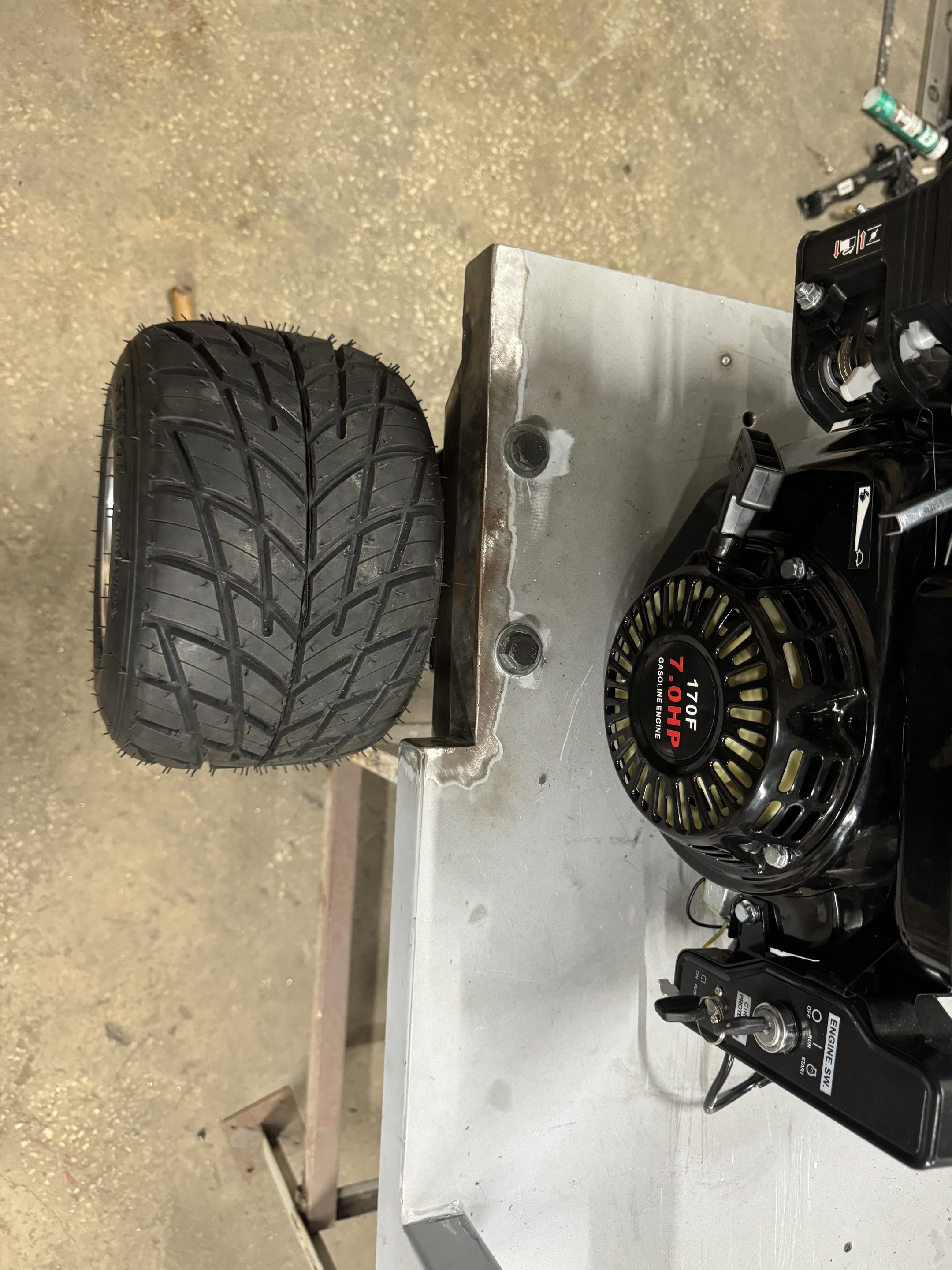
Cut, jigged and MIG-welded from square section steel over the summer of 2024.
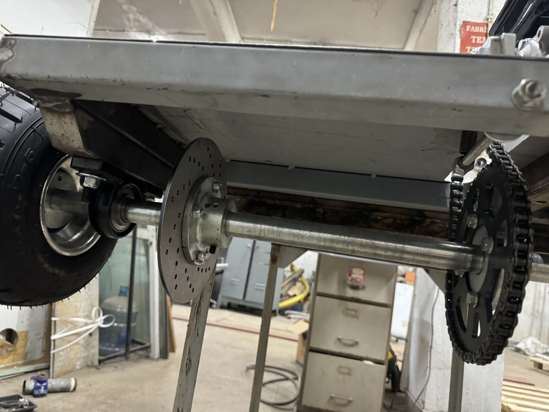
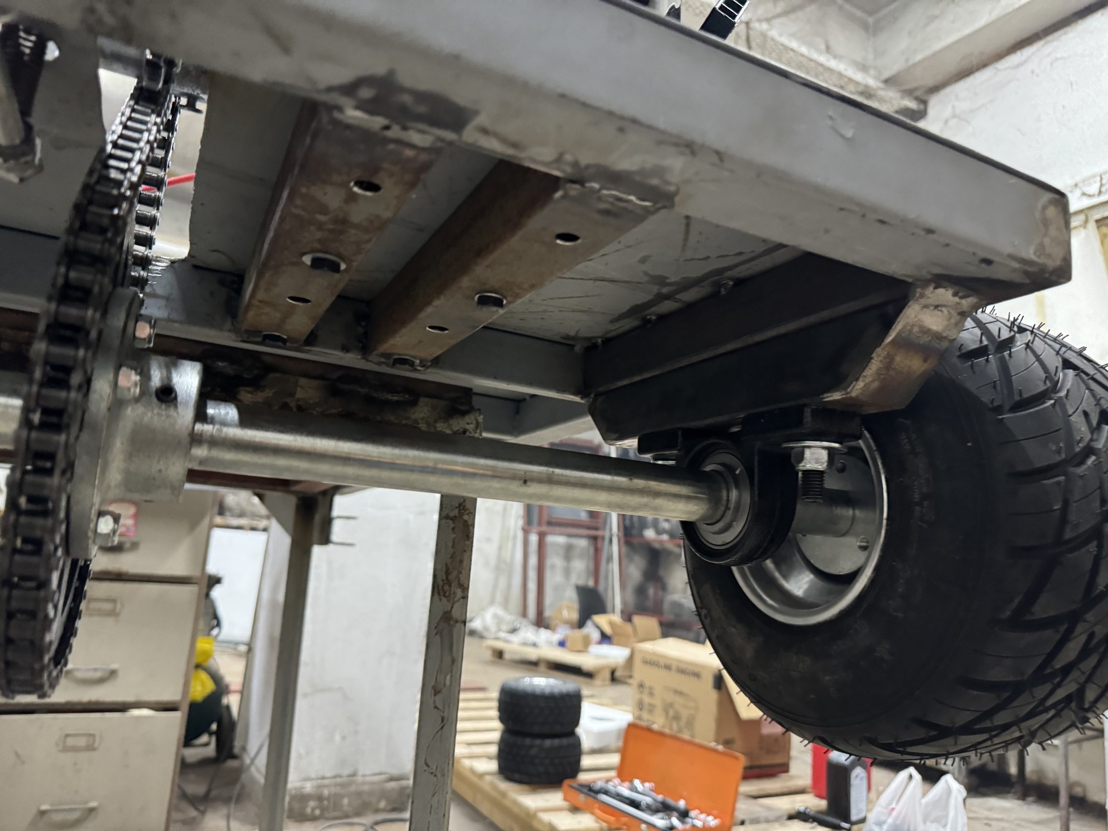
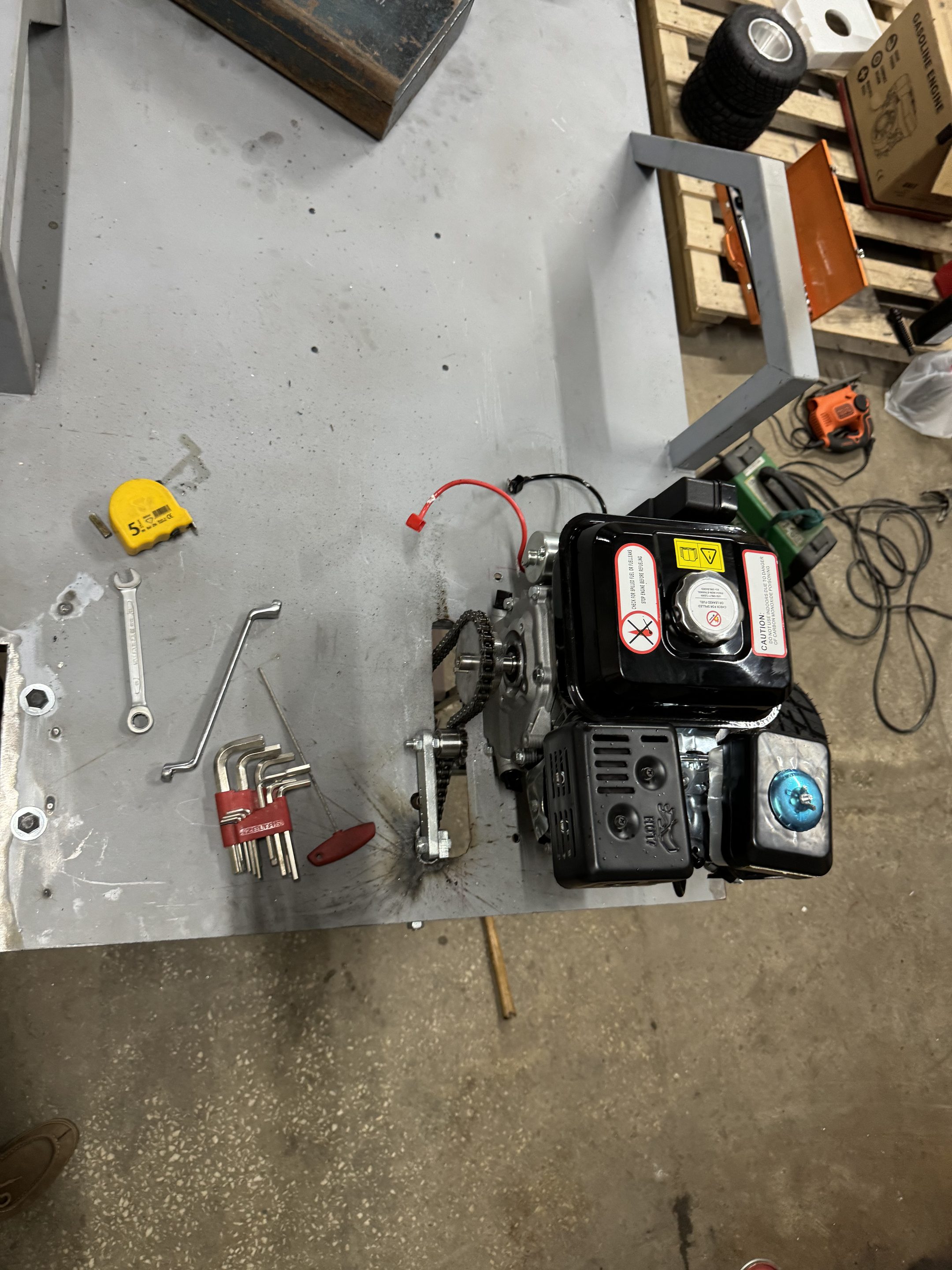
Drivetrain is a 170F 7 hp single-cylinder driving a CVT, then chain to the rear axle. The CVT ratio range is roughly 0.5 to 2.0, chosen to keep the engine near its torque peak across a wide speed range without a gearbox.
What broke
The CVT exploded on the first test.
So right now the frame is good, the axle is good, the engine is good, and the transmission is destroyed. The kart does not drive.
I haven’t finished the failure analysis yet. The candidates are a belt rated below the engine’s torque output, a misalignment between the driver and driven pulleys, or a clutch engagement speed set too low for the load.
Telemetry
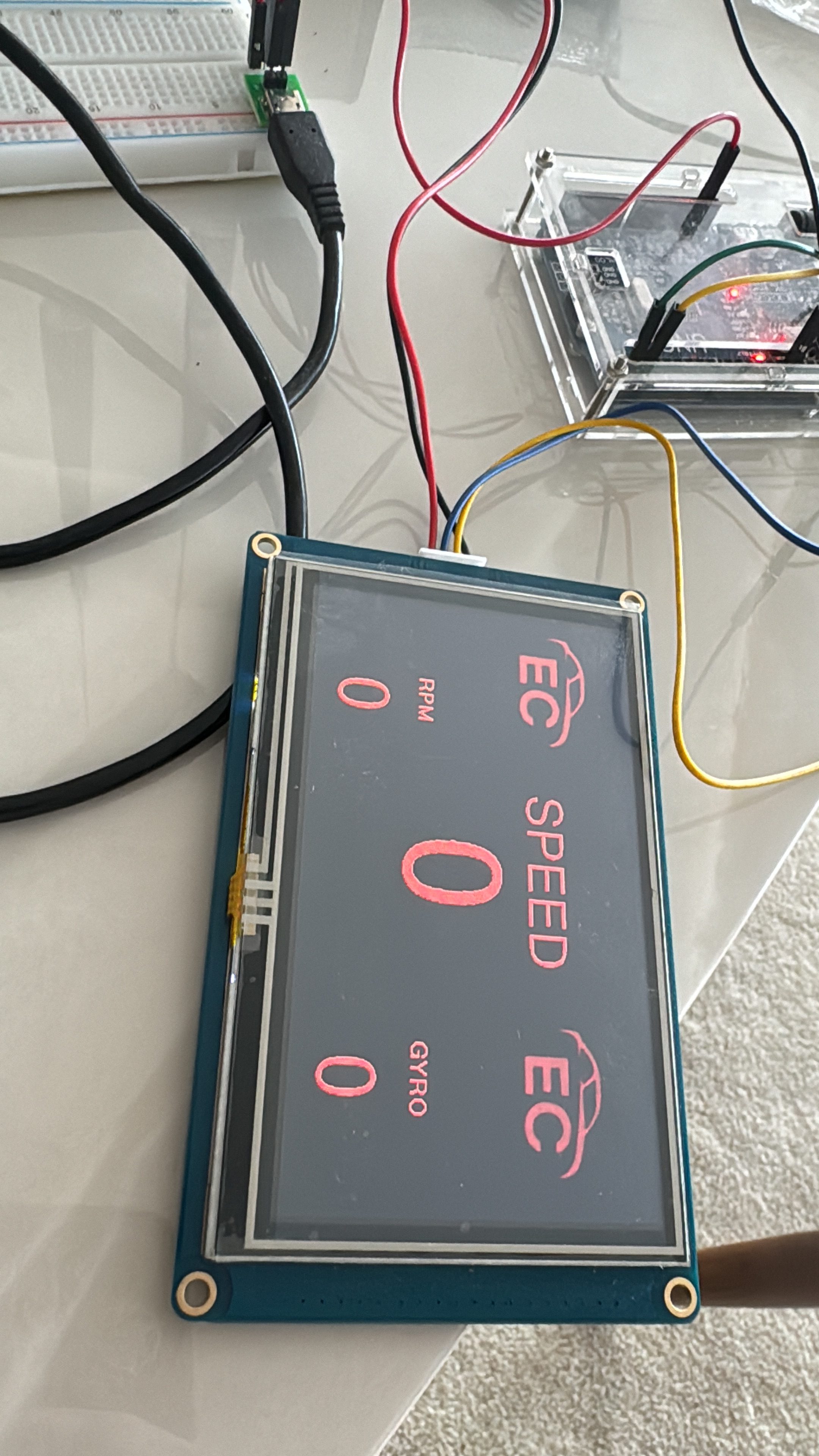
The instrumentation is the part I’ve kept working on regardless. An Arduino UNO reads hall-effect sensors on the axle for wheel speed, an accelerometer for longitudinal and lateral g, and a GPS module for position and ground speed. Output goes to a Nextion HMI with a gauge face I drew myself.
The screen works and the data path works. I don’t trust the numbers yet: the speed channel is uncalibrated, there’s no logging to storage, and nothing is timestamped against anything else, so I can’t correlate a wheel-speed spike with a g trace.
Next
- Root-cause the CVT failure properly before rebuilding the drivetrain.
- Rewrite the telemetry firmware around a real sampling loop with SD logging and a single time base.
- Calibrate wheel speed against GPS ground speed rather than trusting a wheel circumference constant.
- Then drive it, and find out whether the frame behaves the way the CAD said it would.
Tools
Fusion 360 · MIG welding · Arduino IDE · Hall-effect sensors · IMU · GPS · Nextion HMI