A brushless motor, wound by hand
A physics project that turned into my first real encounter with CAD, with 3D printing, and with the difference between a machine that spins and a machine you can put a number on.
The problem
I wanted to know how much of the electrical power going into a brushless motor actually comes out as rotation, and how that fraction changes as the motor spins faster. Buying a motor and testing it would have answered the second half. Building one answered both, because it meant I had to understand every part I would later be measuring.
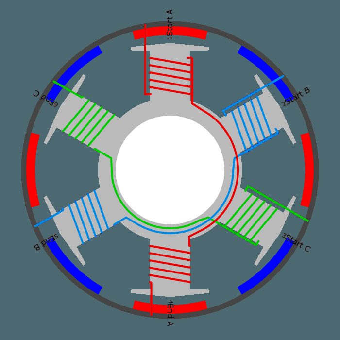
The target was an outrunner brushless DC motor, the type with the rotor on the outside and the stator fixed in the middle, in a six-slot, eight-pole configuration: six wound teeth on the stator against eight neodymium magnets around the inside of the rotor bell, sized around the magnets and a 50 A ESC I already had.
The approach
I sized the winding using a BLDC calculator from Bavaria Direct, then modelled the rotor and stator in Fusion 360. This was the first time I used CAD for something I intended to physically exist, and it’s the reason I ended up applying for engineering.
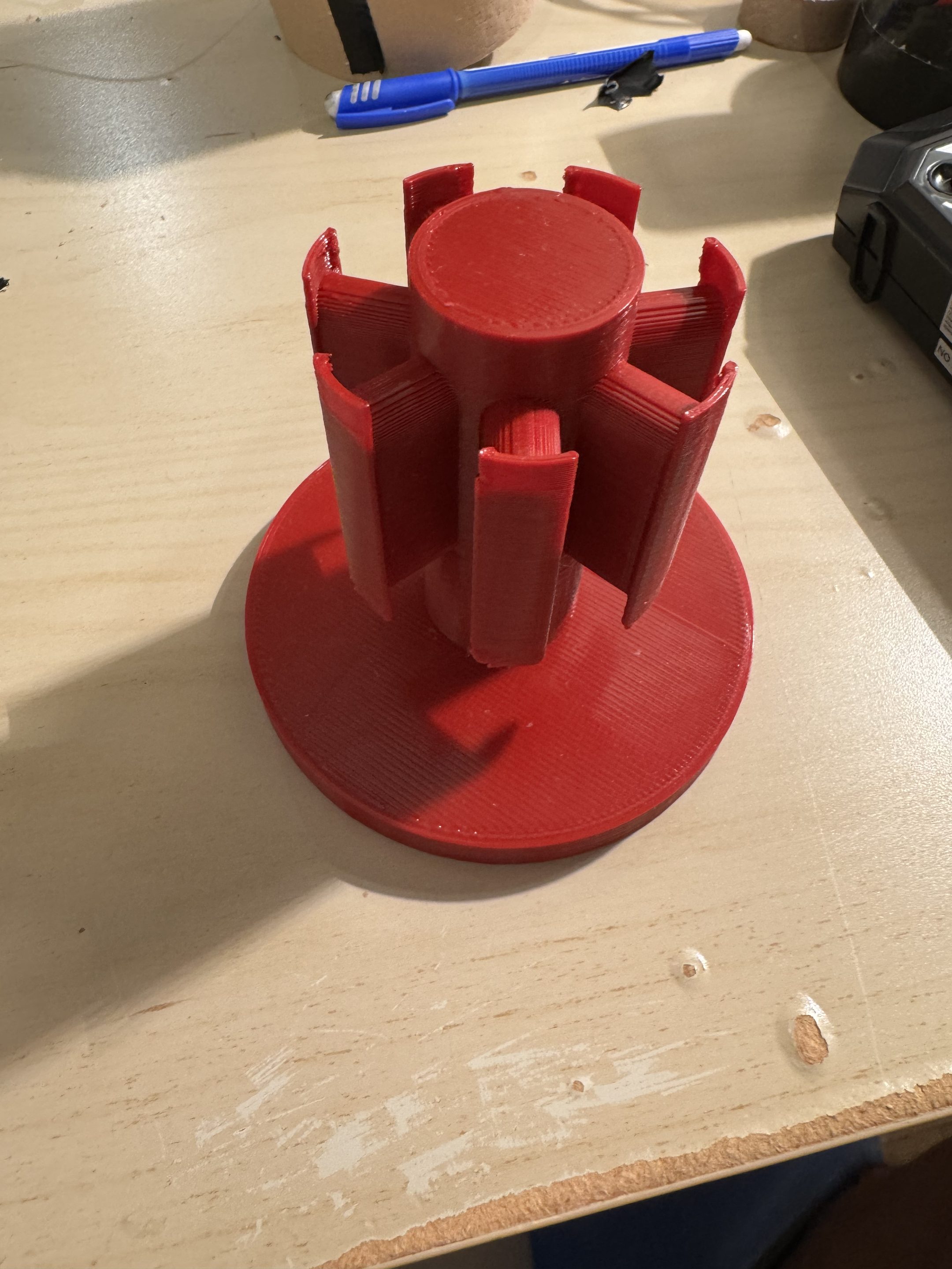
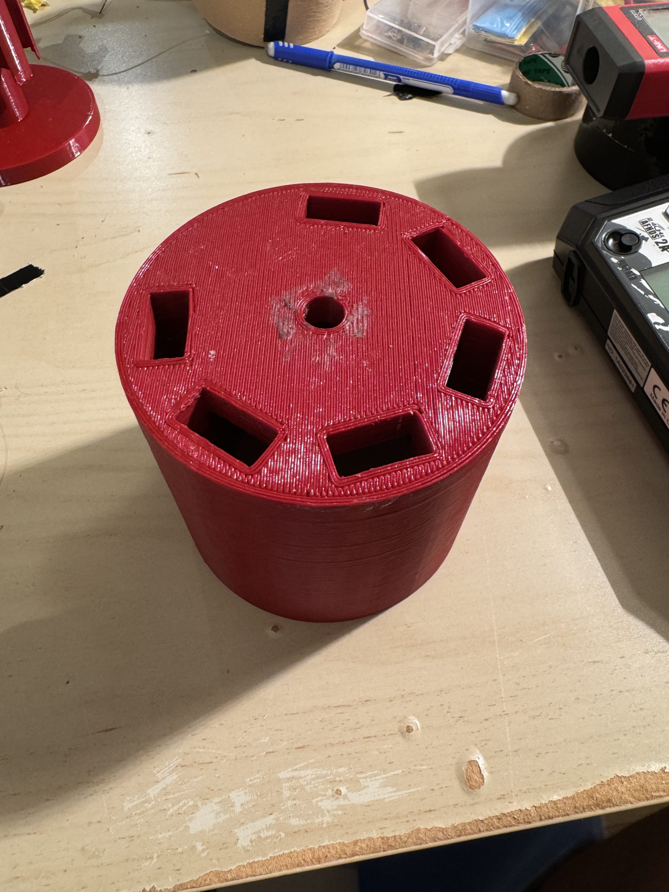
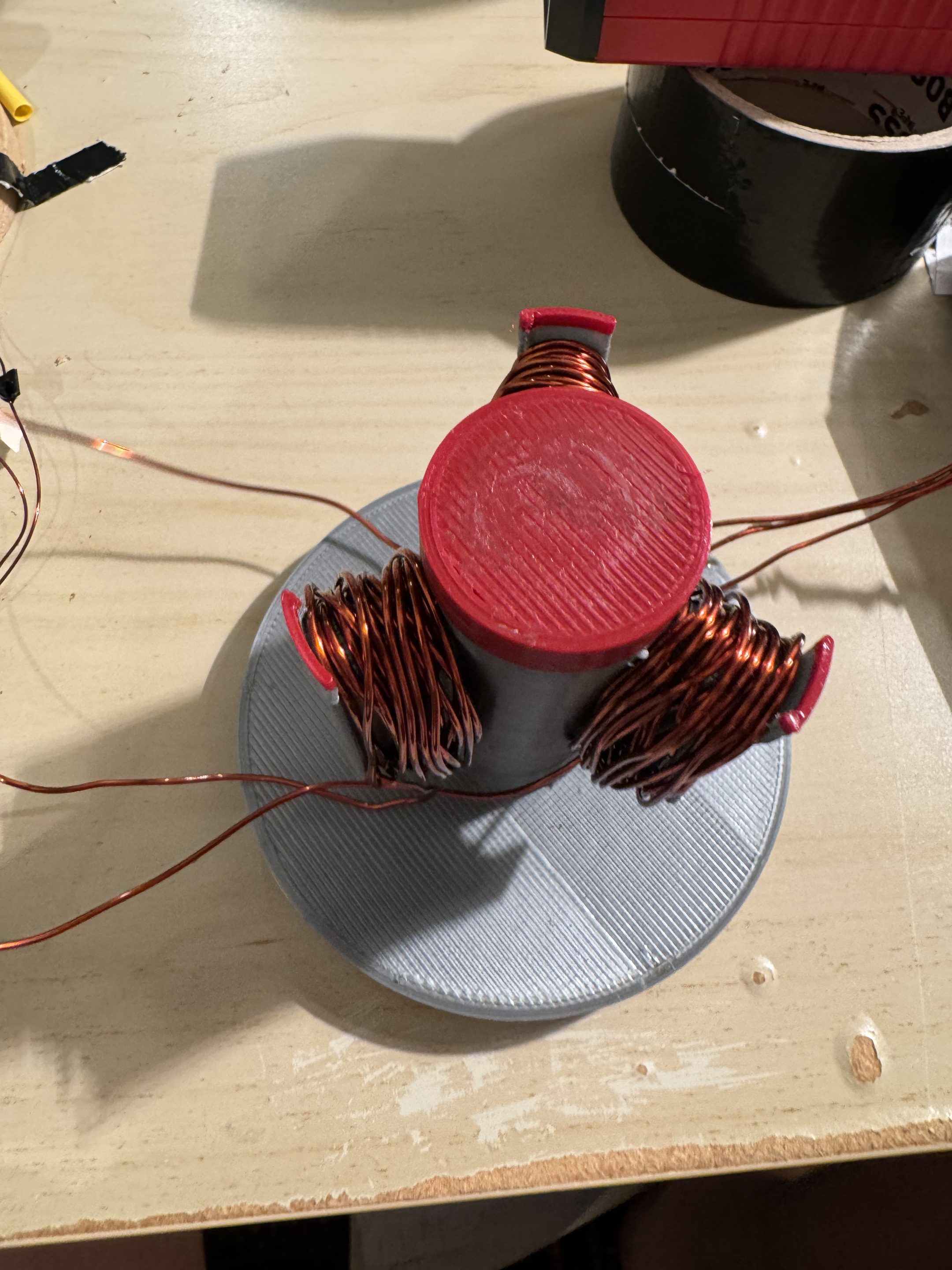
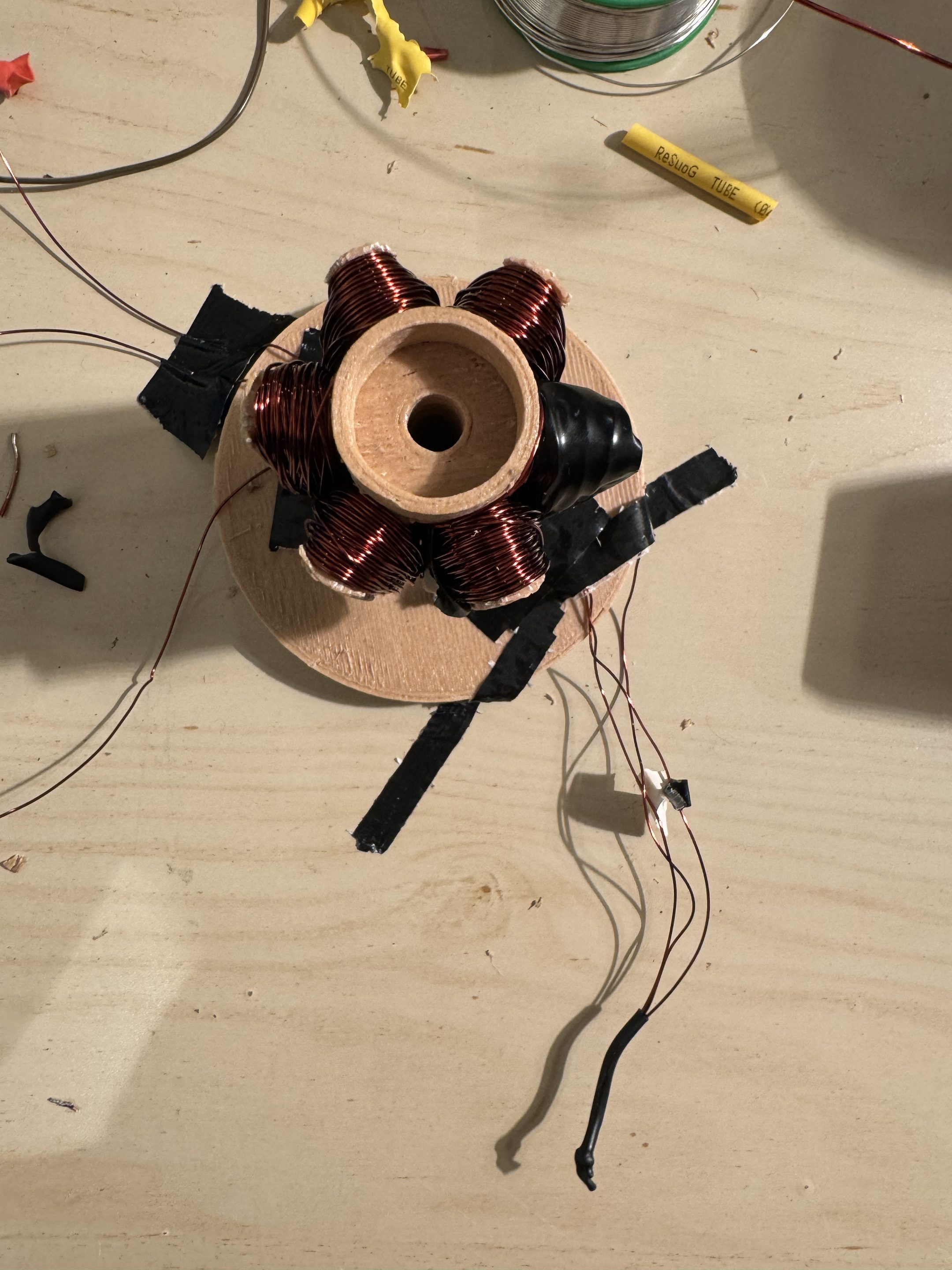
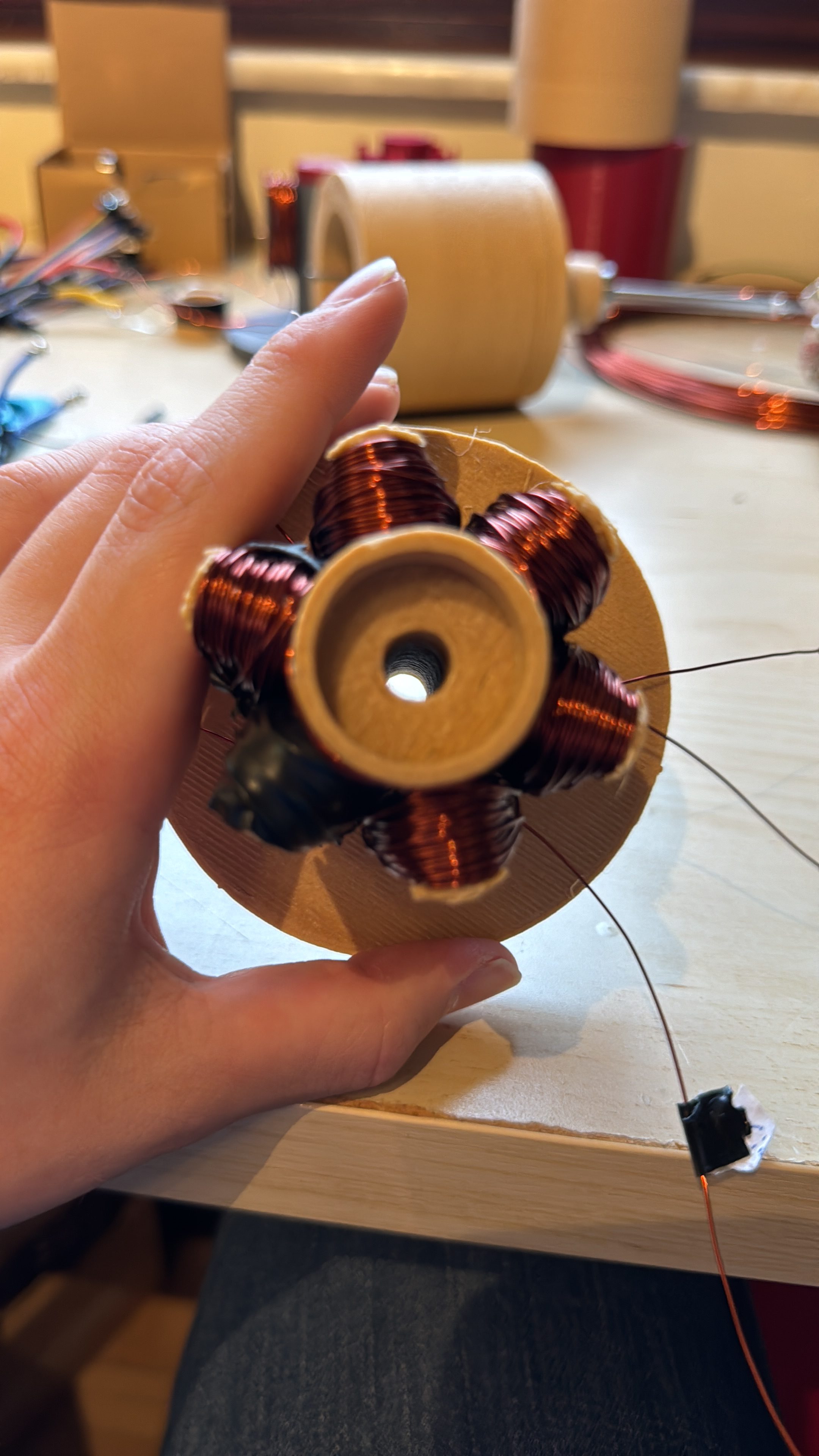
Both parts were printed in PLA. The stator’s six teeth were each wound by hand with enamelled copper wire, three phases in a star configuration, alternating around the circumference against the eight rotor poles.
Nobody warned me about the winding. Slot fill determines torque, and slot fill depends on how neatly you can wrap wire around a printed tooth by hand, under tension, without scratching the enamel. My first attempt was loose and uneven.
What broke
The first rotor stuttered instead of turning.
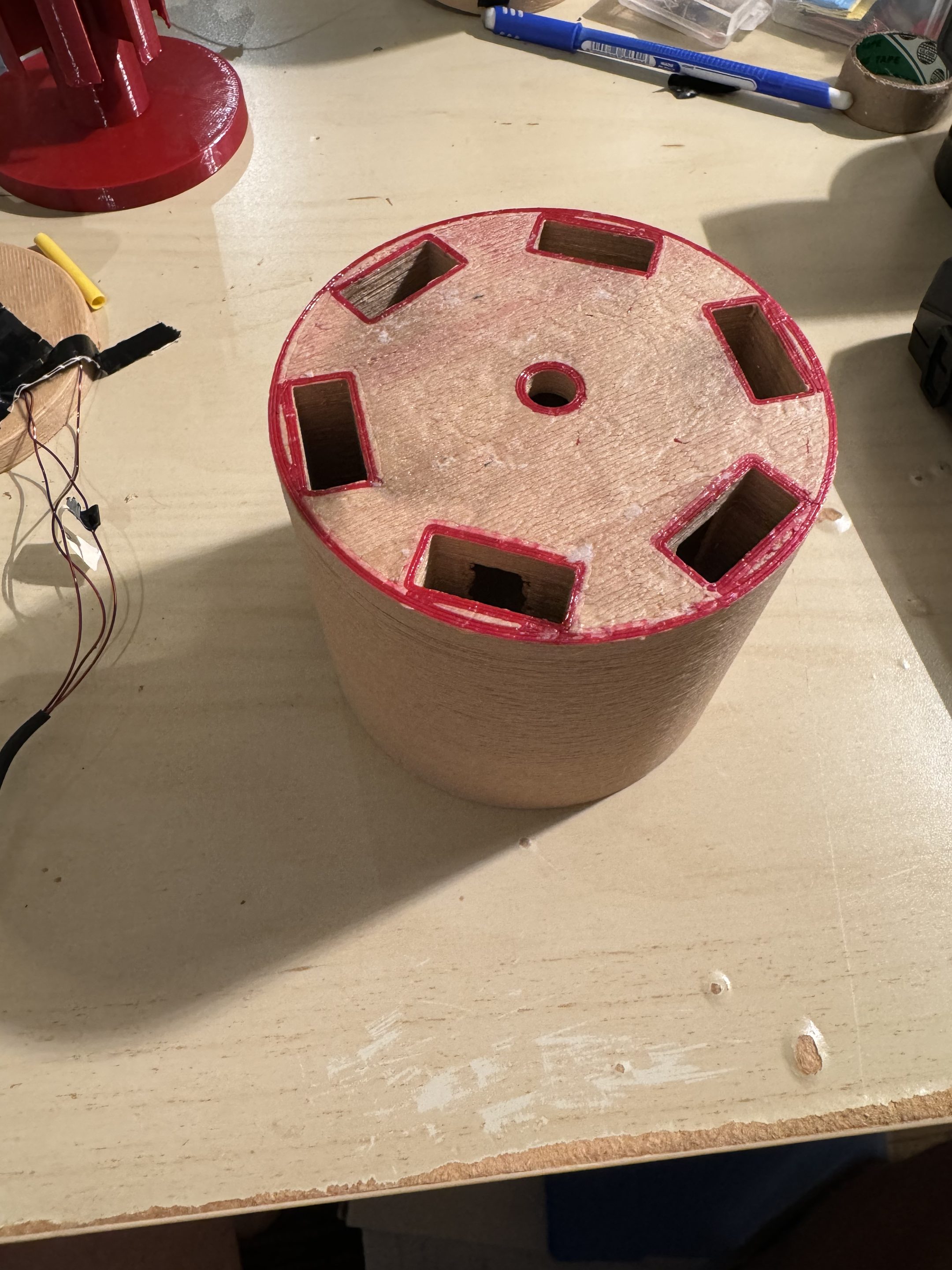
The magnet pocket geometry was wrong. The magnets sat at the wrong spacing relative to the stator teeth, so the field never pulled the rotor cleanly from one commutation step to the next. It would twitch, lock, and twitch again.
I reprinted the rotor with corrected pocket geometry and retuned the ESC’s timing. After that it ran cleanly and held speed under load.
Measuring it
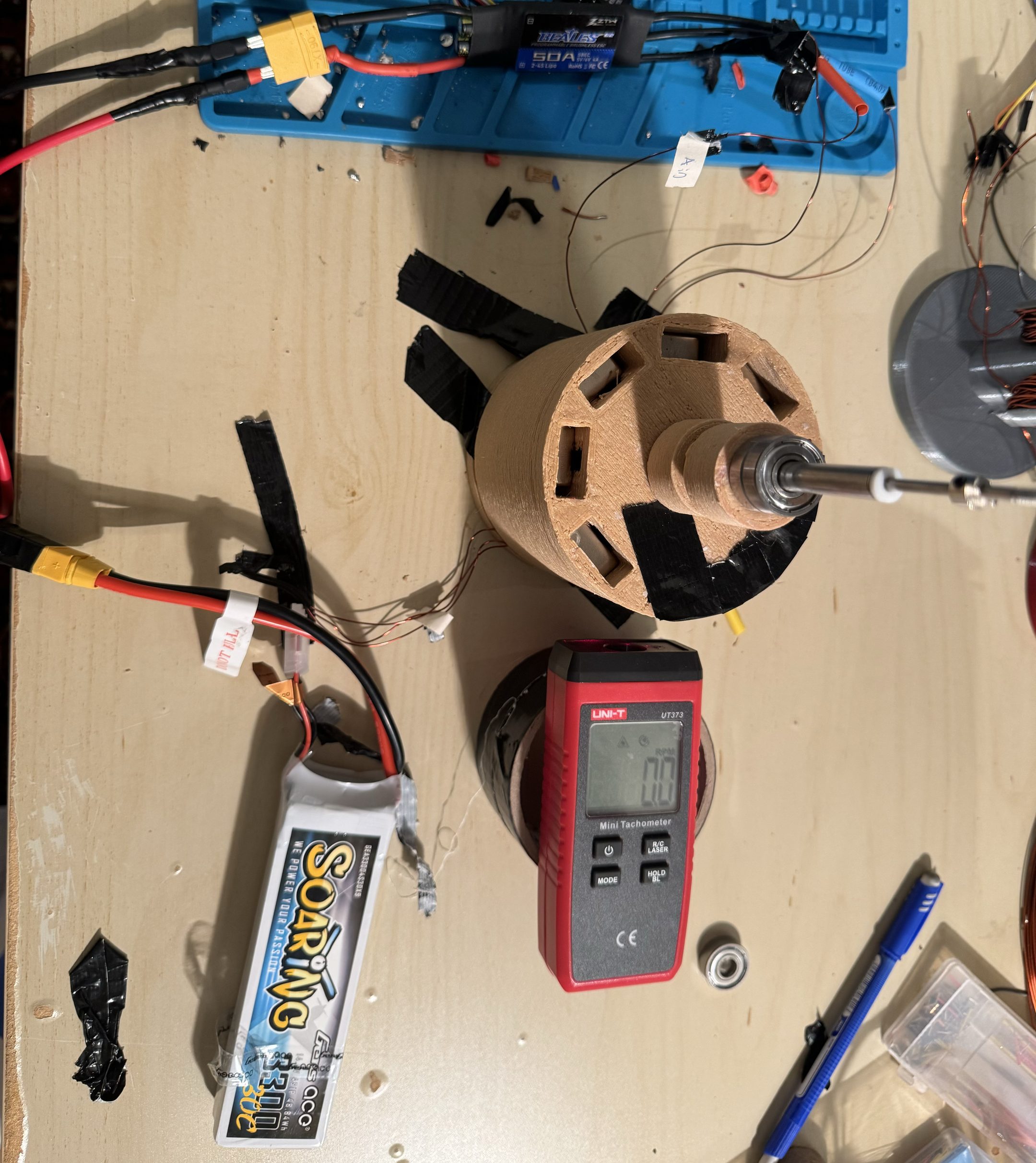
The rig is deliberately simple: 3S LiPo through the ESC into the motor, current and voltage measured on the input side, and a UNI-T UT373 laser tachometer reading a reflective strip on the rotor for output speed.
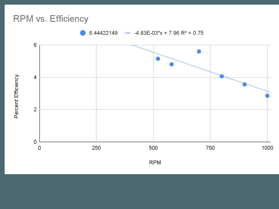
I ran the motor at seven speeds between 500 and 1000 rpm and computed efficiency at each point.
The result
Measured efficiency ran between 2.8% and 5.6% across the tested band, falling as speed increased. The linear fit gives a slope of −4.83×10⁻³ percentage points per rpm with R² = 0.75.
I originally quoted “maximum efficiency, 8%”. That figure is the y-intercept of the fit, the value the trend line extrapolates to at zero rpm. It isn’t a physically meaningful operating point and I never measured it. The number I should have quoted is 5.6%, at the low end of the range I tested. Maximum observed speed was 2000 rpm.
| Speeds tested | 500 – 1000 rpm, 7 points |
|---|---|
| Measured efficiency | 2.8 – 5.6 % |
| Fit | −4.83×10⁻³·x + 7.96 |
| R² | 0.75 |
| Extrapolated intercept | 7.96 % (not a measurement) |
| Max observed speed | 2000 rpm |
Single-digit efficiency is low, and it should be: PLA has no business being a magnetic circuit, hand-wound slot fill is poor, and there’s no laminated iron anywhere in the machine. What I wanted was the trend, and the falloff with speed came through clearly from a motor made of printer filament and copper wire on a kitchen table.
What I would do differently
- Print the stator core with an iron-filled filament, or laminate a real core. Almost all of the loss is here.
- Measure torque directly with a brake rather than inferring output power.
- Extend the speed range. Seven points across 500 rpm is a thin basis for a linear claim, and R² = 0.75 reflects that.
- Wind with a jig. Hand tension isn’t repeatable, and slot fill varied visibly between phases.
Tools
Fusion 360 · FDM 3D printing · 50 A ESC · 3S LiPo · UNI-T UT373 laser tachometer