A robot that climbs a pipe with no code in it
The competition banned microcontrollers outright. So the sequencing had to be built physically: a geared mechanical timer tripping a chain of switches that made the robot behave as though something had programmed it.
The problem
The IMechE Design Challenge 2026, Foundation level, run at UCL as part of ENGF0033. Design and build a fully self-contained robot that climbs a 22 mm copper pipe.
The mission is fixed. Start with the top surface 400 mm off the base. Climb to a barrier at 2.2 m, dragging a chain whose weight increases the higher you get. Stop at the top, switch on a red light and a buzzer, dwell there between 10 and 15 seconds. Descend. Somewhere between the halfway mark and the start, drop the chain. Stop yourself at the bottom. Keep a green light on the whole time. Finish inside three minutes.
Then the constraints that make it interesting:
| Rule 4.13.2 | Analogue circuitry only, non-programmable |
|---|---|
| Rule 4.35 | £50.00 maximum on the IMechE bill of materials |
| Rule 4.23 | No lithium batteries |
| Rule 4.22 | One battery pack for everything |
| Rule 4.1 | Fits inside Ø400 × 300 mm |
| BS EN 1057 | Must not scratch or contaminate the pipe |
No microcontroller. No Arduino, no code, nothing programmable. A robot that has to execute a seven-step timed sequence autonomously, with nothing to execute it.
My part
Six of us, Group 18. I ran the electronics and was one of the three people doing the CAD. I also hosted: we met at my house through the design phase, and I supplied some of the material. In practice I was leading the team.
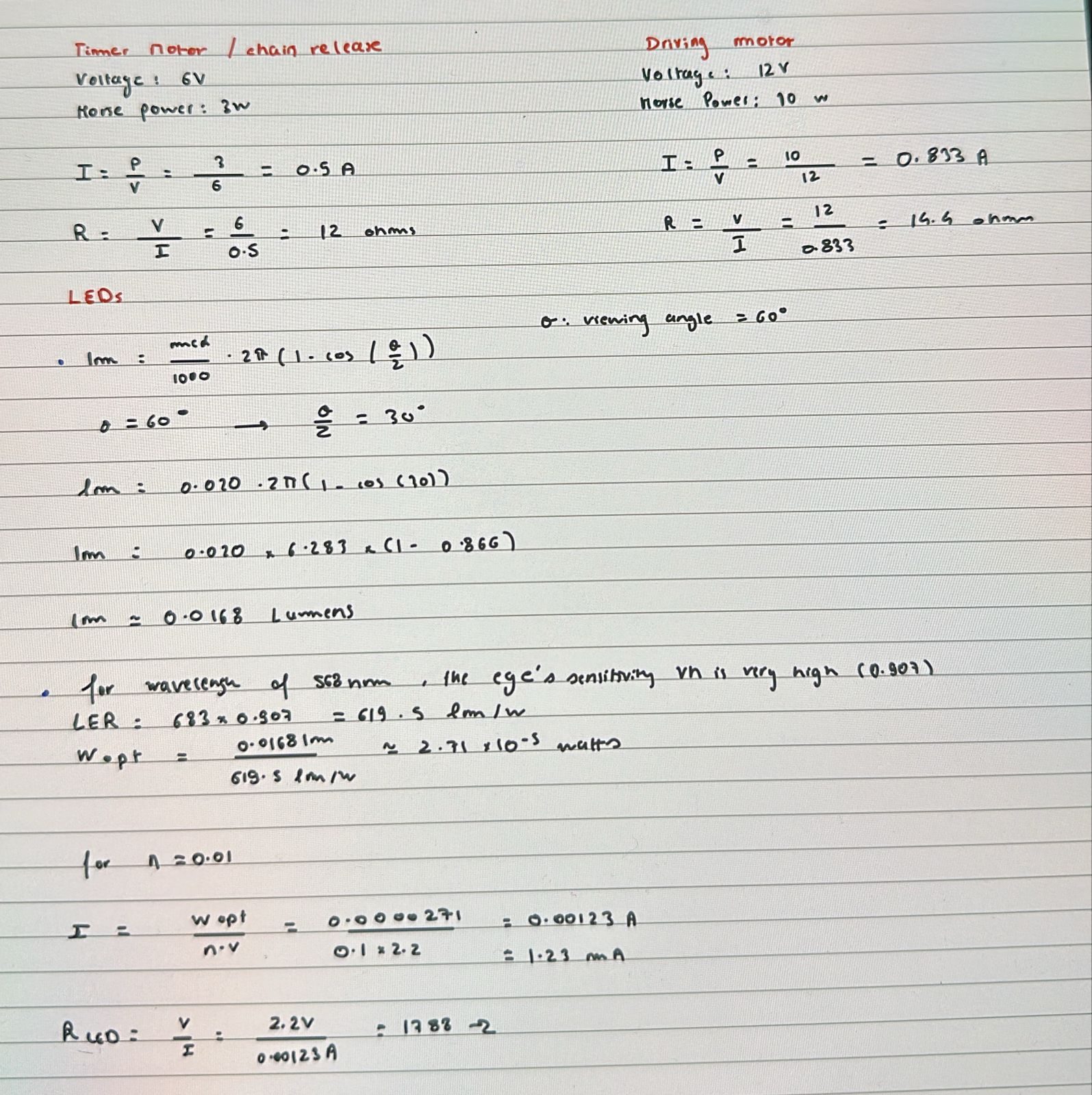
Two things on this page are mine end to end: the switch logic that replaced the forbidden code, and the chain release mechanism.
The switch logic
If you can’t program a sequence, you have to build one. The device runs on a mechanical timer, a geared disc driven by its own small motor that turns one revolution every 16 to 18 seconds, and a set of five lever switches positioned so the timer trips them in order.
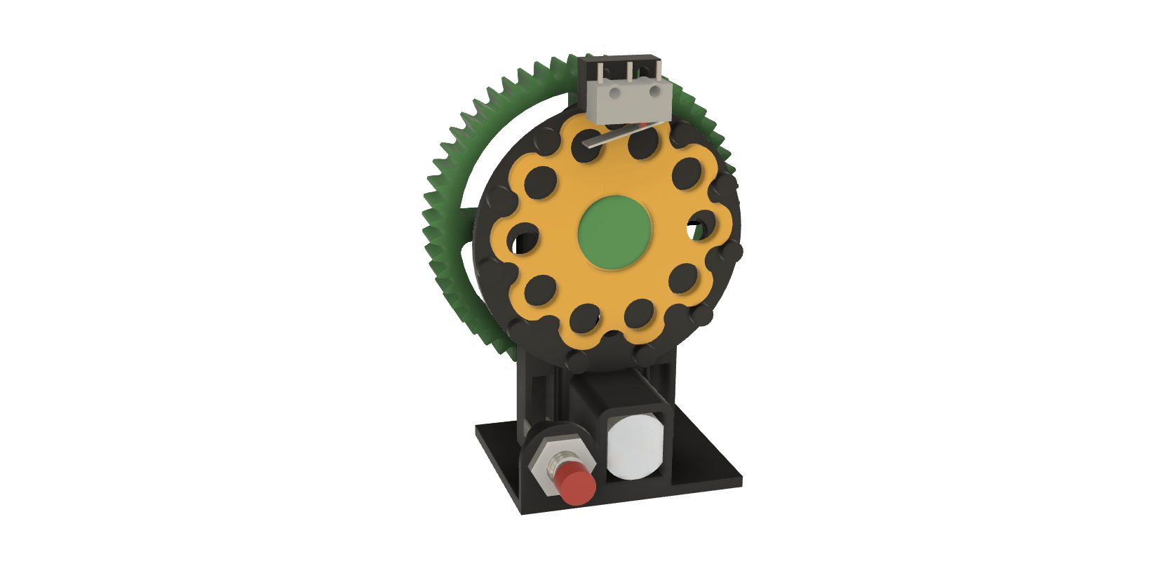
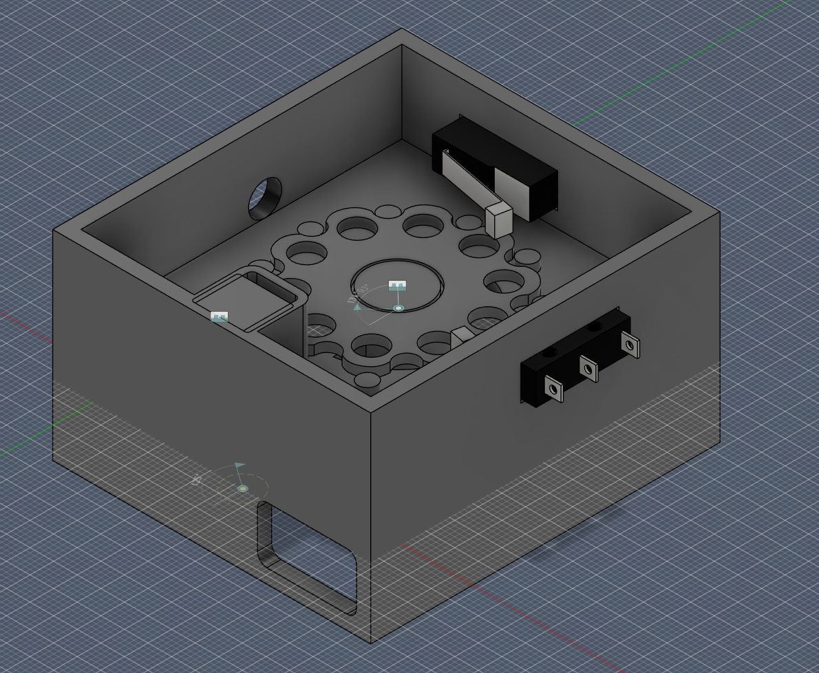
The sequence falls out of the geometry:
- Manual start. Drive motor runs, green LED on, robot climbs.
- The top plate hits the barrier. It is sprung, so it compresses onto a lever switch. The robot senses arrival by being pushed, not by measuring anything.
- That switch starts the timer, lights the red LED and sounds the buzzer.
- One timer revolution later, a second lever reverses polarity to the drive motor. The robot descends. Dwell time is whatever the gear ratio makes it. We tuned it to 12 seconds, mid-band of the 10–15 s the rules reward.
- A further delay trips the release lever, and the chain drops.
There is no state machine anywhere. The whole sequence lives in the angular position of one plastic disc and the gear ratio driving it. Get the ratio right and the robot looks like it knows what it’s doing.
The chain release
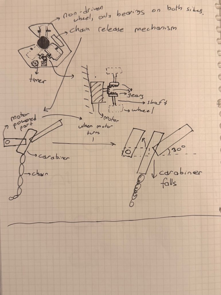
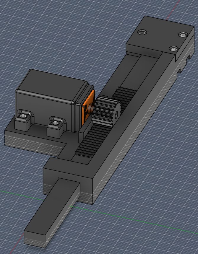
The other piece I owned. The problem: hold a 50 mm carabiner carrying up to 400 g of chain for the whole climb, then let go of it on command, where the command is a switch closing rather than an instruction.
It went through four revisions before landing on a rack and pinion driven by an N20 motor. The pinion drives the rack, the rack withdraws the arm, and past about 30° the carabiner slides off. Nothing has to grip or release. The only actuation is linear travel, and gravity does the separation.
The rest of the machine
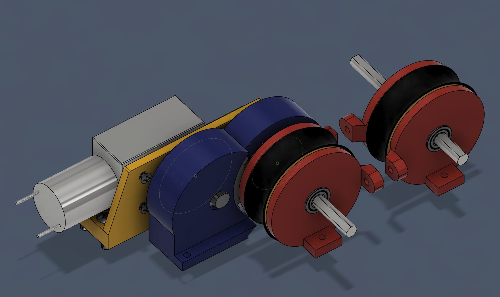
Friction drive: one powered wheel and one idle wheel clamping the pipe between them, pulled together by threaded rods so the clamp force is set by tightening nuts rather than by a spring that could relax. We designed for 50 N normal force, giving a factor of safety of 2.43 against slip on the μ = 0.86 rubber-on-copper interface.
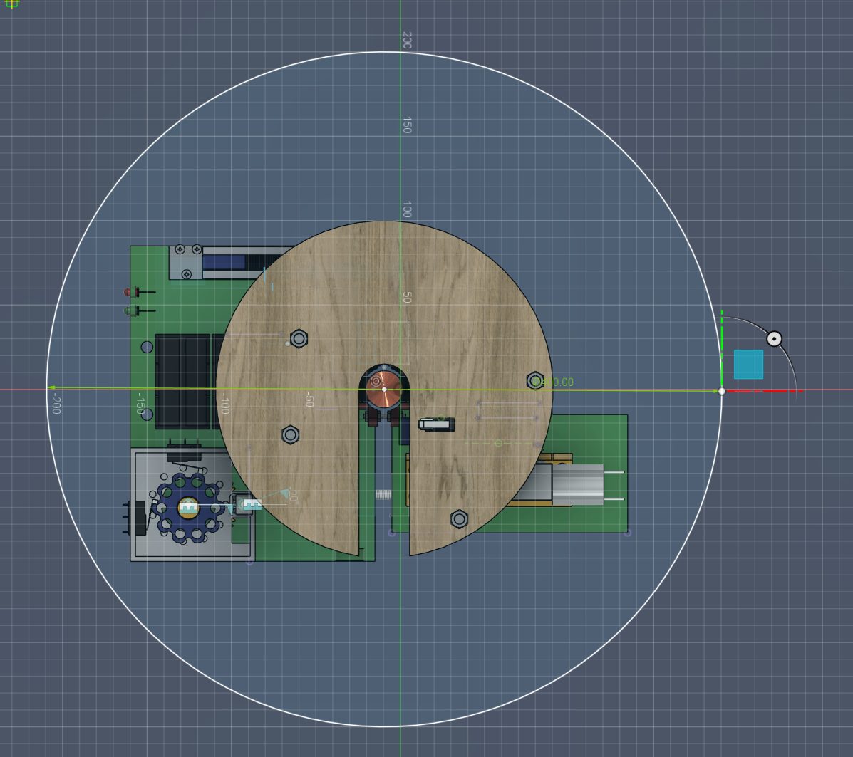
Chassis in laser-cut plywood, split into separate top and bottom bodies so any one subsystem could be pulled and reworked without dismantling the machine. Everything else, from the gearbox and wheels to the timer, release and battery holders, was printed in PLA. Power from a NiMH pack, because lithium was banned.
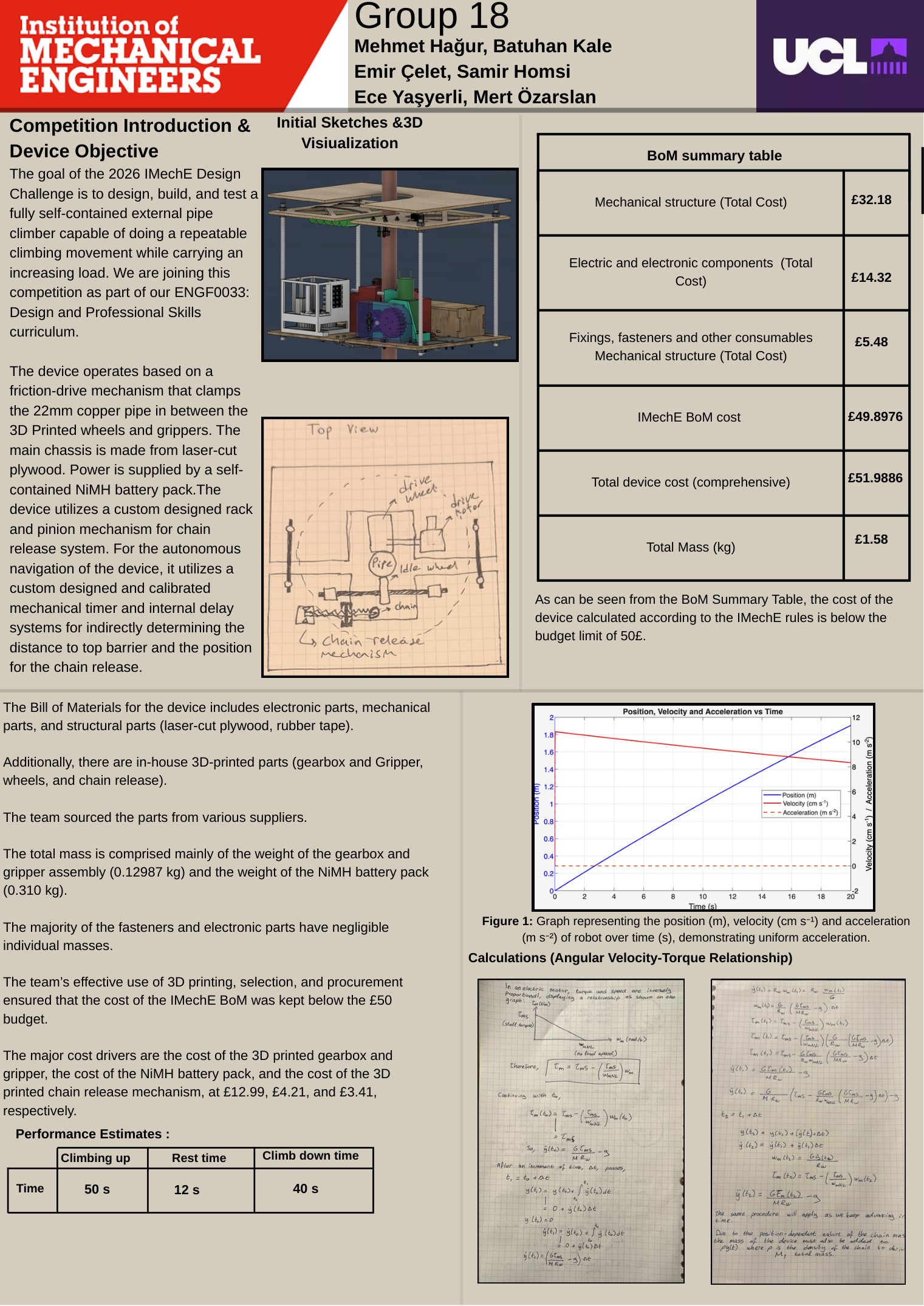
We modelled the motion in Excel rather than closed form, because two things vary continuously: the chain mass grows with height, and motor torque falls with angular velocity. An iterative solve at small time steps handled both.
| Predicted climb | 50 s |
|---|---|
| Dwell | 12 s |
| Descent | 40 s |
| Total | ≈102 s against a 180 s limit |
| Total current draw | 1.83 A against a 10 A fuse |
| Slip factor of safety | 2.43 |
| IMechE BoM | £49.90 against £50.00 |
The BoM line took the most arguing. Ten pence of headroom on a £50 budget came from printing everything we could in-house and questioning every fastener.
What broke
The timer is an open-loop clock, and open-loop clocks drift.
Dwell time, descent distance and the chain release point are all inferred from how far a disc has rotated. The robot never measures where it actually is. A battery sagging under load slows the timer motor, and every downstream event drifts with it. Calibration held on a fresh pack; it was the thing I trusted least.
The proper fix is a limit switch or an encoder referencing real position rather than elapsed rotation. Within the no-programming rule that is harder than it sounds, which is probably why the challenge is set that way.
Result
Second out of more than fifty UCL teams.
The takeaway for me was that sequencing doesn’t need software. It’s a mechanical problem that happens to have been solved in code for the last forty years, and a disc, a gear ratio and five switches will do it. Slightly worse, far cheaper, and it can’t crash.
Tools
Fusion 360 · Analogue switch logic · FDM 3D printing · Laser cutting · Excel dynamic simulation